Parabolic Discone
by
Mike Lake KD8CIK
Why - Designing/Math - Building
one - Stacking - Applications
-
The idea
Also, see my article on eHam.net.
| Note: There is nothing wrong with this design, other than being
"new and unusual". The physics is obvious to anyone who honestly
understands what is going on. Armchair experts have complained that
this is a useless idea, amazing me with how foolish many people are.
Because the Parabolic Discone is not limited by the problems of traditional
designs, anyone can "upsize it" to make the highest gain omni ever made!
It looks like I may break that record myself despite being paralyzed because
no one else seems to be interested. I currently have the materials
for a 12 foot version, except for a good transmitter. Demonstrating
24 dbi of omni directional gain or better should make a point.
Like many "new" antenna designs, the basic principles have already been
proven in optics many years earlier. You can invent your own new
design by finding a useful optical principle and applying it to antennas.
Hell, they will even give you a patent for re-applying optical principles
to antennas. (Many antenna patents, like for parabolic dish designs,
are in principle only copies of earlier optical designs. Light and
radio waves are different frequencies of the same thing so it should be
obvious!) |
Also see my first article on eHam.net.
(printable images) |
-
Gain like a parabolic dish but omni-directional with the wide bandwidth
of a discone antenna.
-
A dipole or other driven element could also be used at the focus.
-
Vertical polarization if vertically polarized at the focus.
-
May be stacked for gain improvement, but bandwidth issues result.
-
Overhead reflector can be raised higher, like a periscope antenna.
-
Idea has been proven with sound and light for omnidirectional gain.
|
Why make a Parabolic Discone antenna?
The first advantage of the Parabolic Discone is wide bandwidth plus
gain in an omni-directional antenna. Traditional omni-directional
antennas with gain can only operate over a narrow bandwidth effectively.
Another advantage of the Parabolic Discone is that other omni-directional
antennas with gain require tuning and phasing to work well, but not this
antenna.
The gain vs. size of the Parabolic Discone grows like a traditional
"Parabolic Dish." The difference is that gain in the Parabolic Discone
causes the RF field to flatten out into a "pancake" at higher levels of
gain. The gain increases with frequency like a dish antenna.
Doubling the size causes 3 db of gain, doubling the frequency results in
3 db of gain.
The length of the overhead cone is roughly equal to a fixed frequency
omni of similar gain. However, fixed frequency omni antennas have
limits of useful gain and highest frequency that they can be made for.
The Parabolic reflector in conjunction with the overhead cone reflector
are only limited by how big and precise you can build them!
You could alter the angles of the overhead cone reflector if your wanted
to "steer" the signal up or down from horizontal. This would be helpful
if you wanted to use a Parabolic Discone as a repeater antenna and did
not want gain that was purely horizontal.
You can also put the parabolic section on the ground and mount the cone
reflector higher, like a periscope antenna. The overhead cone reflector
may need to be made bigger, depending on the beamwidth of the parabolic
section. The cone could be composed of many evenly spaced rods attached
to a point because the RF is verticality polarized.
Designing a Parabolic Discone - the Math
Henry O'Tani (G8OTA) suggested
that the gain should be the square root of a "normal" parabolic dish, because
of the spreading from one dimension to two dimensions caused by the cone
(half the dB gain value).
Instead of making a single Parabolic Discone bigger, it may be possible
to use stacked Parabolic Discones. The problem is that gain and pattern
distortion can result. This is because you have some of the same
considerations that influence dipole based collinear antennas.
Calculated omnidirectional gain over isotropic for an ideal Parabolic
Discone:
(note: These figures still need to be verified as of 4-4-06.
One db of illumination loss has already been subtracted.)
|
18 inch |
3 foot |
6 foot |
12 foot |
24 foot |
| 144 MHz |
. |
. |
. |
6 |
9 |
| 220 MHz |
. |
. |
5 |
8 |
11 |
| 440 MHz |
. |
5 |
8 |
11 |
14 |
| 900 MHz |
5 |
8 |
11 |
14 |
17 |
| 1200 MHz |
6 |
9 |
12 |
15 |
18 |
| 2.4 GHz |
9 |
12 |
15 |
18 |
21 |
| 5.0 GHz |
12 |
15 |
18 |
21 |
24 |
| 10 GHz |
15 |
18 |
21 |
24 |
27 |
| 24 GHz |
19 |
22 |
25 |
28 |
31 |
| 47 GHz |
22 |
25 |
28 |
31 |
34 |
| 149 GHz |
27 |
30 |
33 |
36 |
39 |
| 250 GHz |
29 |
32 |
35 |
38 |
41 |
(Let me know if you need over 250GHz.)
I am asking for help to develop the equations for this antenna.
Unfortunately medical problems from being paralyzed, including fatigue,
have prevented me from figuring it out for myself. I will also provide
links.
One thing to note is that the some of the RF from the driven element
does not get reflected by the parabolic section, it escapes at higher angles.
A compromise is necessary for how high you make the parabolic section vs.
the end results.
Too much gain may cause a problem in some applications. As the
field narrows with increasing gain, the antennas at the other end might
be to high or low for the best gain. This is true for any omni directional
antenna with gain.
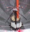
Building a 24 Inch Stressed Parabolic Discone
The pictured two foot wide parabolic discone was constructed out of
16 pieces of steel rod covered with aluminum window screening for the parabola.
Galvanized sheet steel was used for the overhead cone reflector.
The discone element at the focus is made out of wire, cut for a 1200 Mhz
low frequency.
The parabolic section was built on the end of a pipe fitted with a piece
of hardwood dowel inside. Using a drill bit slightly larger than
the rods, 16 evenly spaced holes were drilled around the pipe one inch
from the top. Pieces of rod 18 inches long are then stuck into the
holes. The rod is 0.078 'music wire'' from K&S Engineering,
# 505 (bought at a toy/hobby store).
A central "mast" made from a fiberglass rod is stuck slightly off center
into the wood fitted in the pipe. A short piece of PVC pipe is attached
on the fiberglass rod using nylon wire ties, by putting the rod up though
the ties and pipe. Fishing line is used to pull each of the steel
rods into a parabolic shape by tightening and attaching the line to the
piece of PVC pipe. After tightening all the rods a line was run along
the outside edge. "Plastic Dip" was used at all the attachment points
to keep them from slipping.
Aluminum window screening is attached by tightly weaving a thin copper
wire between the screening and the rods. The necessary precision
of the resulting parabolic section depends on the gain and highest frequency
desired.
 |
The overhead cone is cut from sheet metal by making a circle with an
18 inch radius as long as the intended distance from tip to edge.
A notch is cut from the edge to the center then the metal pulled into a
cone. It is best to practice on a scale model cut from a piece of
paper first. |
Update on May 11, 2006:
The driven element for the 24 inch Parabolic Discone was constructed
out of wire using VE3SQB's discone design program for 1200 Mhz operation.
Download the program from his website:
http://www.ve3sqb.com/
Remember to design the discone for the lowest frequency of desired operation.
Also note that good transmitting SWR usually exists up to 3x the lowest
frequency, though reception should be good up to 10x the lowest frequency.
The entire Parabolic Discone has a lowest frequency that it will work
at, so look at the table in "Designing a Parabolic Discone"
for an idea. Gains of less than 6 db may require changing the height
of the focus and the height of the parabolic section. The 24 inch
Parabolic Discone in theory has a gain of appx. 7db at 1200 MHz.
I verified over 6db of gain at 2.4 and 5.8 GHz based on transmission distance.
(Sorry for forgetting the obvious step of making the discone part.
Without a driven element the other parts will not do much!)
Equation to verify the parabolic shape:
y= x2 / ( 4 * focus distance) ==> y= x2
/ ( 4 * 3) ==> y= x2 / ( 12 )
Graph for confirming the curve of the parabola:
(3 inch high focus point and 12 inch radius)
| x |
y |
| 1 |
0.083 |
| 2 |
0.333 |
| 3 |
0.75 |
| 4 |
1.333 |
| 5 |
2.083 |
| 6 |
3 |
| 7 |
4.083 |
| 8 |
5.333 |
| 9 |
6.75 |
| 10 |
8.333 |
| 11 |
10.083 |
| 12 |
12 |
|
 |
Stacking Parabolic Discones
|
Collinear stacking may be an option instead of building larger parabolic
discones. In theory you could achieve 3 db of gain by stacking two
identical parabolic discones. I believe this should provide
better results than stacking regular discones because the radiated waves
are already "straighter" over a wider bandwidth.
I have experimented with a set of one foot parabolic discones at 5.8
GHz and observed appx. 1 db of gain. My limited results are likely
due to loss and impedance issues in my test setup. I simply split
the RF from one 50 ohm coax into two equal length 50 ohm coax using a BNC
"T" splitter.
More experimentation with stacked parabolic discones may be worth the
effort because of the space savings. A low loss way to drive the
stacked antennas may make stacking useful. |
Applications:
-
Wireless Networks- see Wlan.org.uk
for license exempt Wireless Networks.
-
Multi-band Amateur Radio Repeaters using one antenna
-
"Police Scanner" antenna with gain.
-
Military applications, like as part of a phased direction finding antenna
with gain.
-
Anywhere a high gain with wide bandwidth omni-directional antenna could
be useful
The Idea for the Parabolic Discone
I like the Discone Antenna for it's wide bandwidth, but gain seemed
impossible. Arrays of discones would not have useful results because
the phase and necessary distances will change with frequency. Only
by using the discone with a parabolic reflector was it possible to achieve
predictable and useful results.
The idea for the Parabolic Discone antenna came to me because "dish
antennas" are best understood using the "ray" principle, like light.
So, anything you can do with light you can do with radio waves (in theory).
Looking at antenna design like it was optics can inspire new ideas.
The downside is that antennas must be large in terms of wavelength for
ray principles to apply.
| Let me know if you build a Parabolic Discone,
and the results. I will add links on request for anyone who builds
one of these antennas. |
e-mail: admin@H-a-m-Domain.com
(without the dashes).
(I added the dashes to reduce spam. Let them spam a non-existant
website!)
See my other efforts:
1. Liquid Metal
Antenna and Elastic Stretchable Liquid Metal wire
2. About me on
hamdomain.com
For a website with links to other antenna projects, I recommend:
AC6V.com
PS: Yes, the para-discone appears to be an original concept by
myself. I am paralyzed and did not have the money, time, and energy
to get a patent. Fatigue and other medical problems limit my free time
to what I am desperate to get done. (It is hard to focus when your
bladder feels like it is turning inside out.) Give me the respect
of being the "inventor" and that may be better than nothing. I might
keep giving away patentable ideas for free.
| * I am being called a terrorist,
please help!:
It is hard to talk about what happened because it started with over
six months of harassment while trying to keep my job in Bowling Green,
Ohio. Beginning in 1998 a coworker convinced me to join the Jaycees
civic group he was in. It
ended with harassment that I was a criminal and a terrorist.
Why?!!! I upset VIP's from Bowling Green who were in the group
by complaining about their conduct. So they exploited my weakness
diagnosed in the army. I had bipolar disorder, a mental illness.
This gave the VIP's the ability to attack me as a nutcase "waiting to go
postal" and kill them all. Their revenge was very detailed!
The prosecutor of Bowling Green Ohio was a member of the Jaycees looking
for status, so he assisted the group in what appeared to be criminal harassment
against me. When I tried to make criminal complaints no one took
me seriously because the group had planned ahead. See the website
below for the letter the prosecutor wrote me saying that he was not interested.
I am lucky that out of fear and anger about the harassment I had written
many letters which were documented as evidence to show how crazy I was
becoming. Those officially recorded letters show my mental distress,
and the group makes it clear that it was not concerned if it was causing
me more psychological harm. That demonstrates criminal intent!
See my WhyHope.com
website for details of the harassment by the Jaycees.
I had kept it secret from my ham radio activities, but now I have put
in a criminal complaint to stop the conspiracy and menacing by stalking
that the prosecutor and group committed. This is certain to upset
VIP's, so you might never see me again. The nightmares from the harassment
keep me from enjoying life, so I must take the risk. |
© Copyright 2006 - Michael John Lake - Make copies for personal
use only.